
-
iPhone Thermal Analysis
 All phones from all manufacturers overheat! Including the newest iPhone 6 from Apple. Multiple causes can produce overheating issues, but something is certain, companies invest significant resources to make sure their products are well designed and meet all thermal specifications, and sometimes the efforts fail.
In this article we build a thermal model for iPhone 4. This model will be used later in a future blog for a more detailed thermal analysis. Recent iPhones (5 and 6) follow similar thermal design to the iPhone 4. They have changed in power dissipation (better performance), size, construction, and housing-materials, but in general, the thermal architecture remained unchanged.
The thermal (and CAD) model will be reconstructed from the original phone. Please check iFixit for details on the iPhone 4 teardown. Although most of the dimensions and geometry can be measured, many assumptions have to be made. Fortunately, the final results seemed to agree very well with real measurements.
After opening the iPhone we discovered graphite sheets glued to two shielding cans; highlighted in black in the Figure 1.
Graphite is an excellent heat spreader due to its high in-plane thermal conductivity (400-1500 Wm
 K), and low through-plane conductivity (<4 WmK) . After a close inspection, it seems that these graphite sheets provide heat spreading for the CPU (A4) and LTE modem, located on the opposite side of the board, rather than the eMMCs, DDR and baseband, which are covered by the shielding cans where graphite is applied. This is corroborated later with simulations. The tiny graphite sheet on Figure 1 (b) does not seem to help at all and it might be an expensive piece due to its asymmetrical geometry. I am guessing that the thick flex cable next to it works better as a heat spreader.
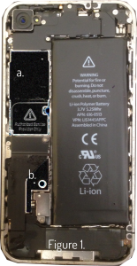
Figure 1. iPhone 4 main board with graphite sheets a. and b.
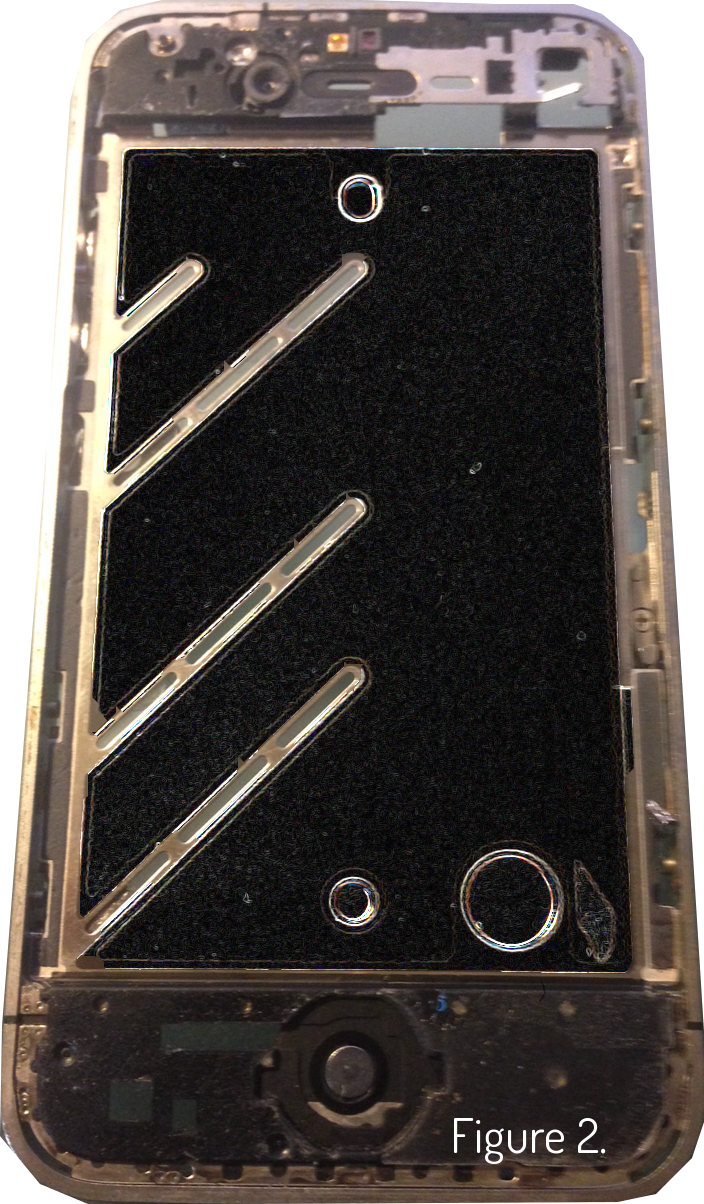
Removing the display exposes another graphite sheet glued to the mid-frame metal support (Figure 2). This spreader helps to mitigate some of the heat coming from the backlight LEDs, and main board.
This graphite sheet covers the entire area of the mid-frame support except on the areas with cutouts but it could have been optimized in size and geometry. This will be investigated later, in a second part of this article.
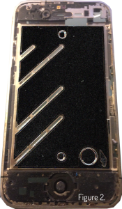
Figure 2. Graphite sheet on mid-frame metal support.
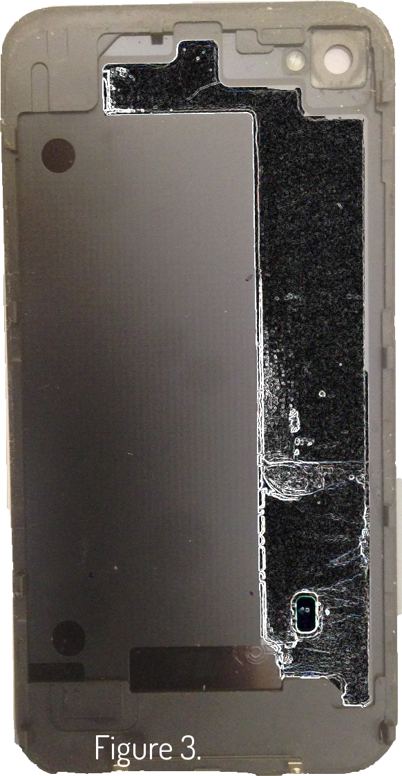
Finally, a fourth graphite sheet is glued to the plastic internal cover (Figure 3). This graphite sheet follows the shape of the main board.
This graphite sheet will be very inefficient for cases when there is little temperature gradient across the length of the board, for examples when the CPU and the LTE modem both are being stressed (thermally) to similar values as they are located on opposite ends of the board (see board layout for better understanding).

Figure 3. Graphite sheet on inner side of rear cover.
I am sure that Apple has a reason for every shape, size, color (or coatings?), and orientation of every spreader, or thermal pad (by the way only the LTE-ICs have thermal pads) that they used with the intention of providing thermal relief . Some make no sense from outside. Besides a significant chunk of the thermal mitigation comes from thermal control implemented with software algorithms to optimize power consumption. What or how is implemented will be always a mystery. My wife says that her iPhone starts acting crazy and on its own when it gets too hot.
Results
Measurements were taken directly from an iPhone 4 to build a semi-detailed thermal model. Special attention was given to all conduction paths, air gaps and thermal solutions that the main components encounter on their path to the external housing, where heat is dissipated by convection and radiation. A detail model of the display was very difficult to re-create, but the location of the backlight-LEDs (main heat source for the display) and thicknesses of the cover glass, touch panel and LCD were captured as accurate as possible. Also the distances from the main board to the front and back covers are believed to be accurate as well.
All shielding cans were assumed to be stainless steel (SUS 304). The mid-frame support was assumed to be aluminium (Al-6063). The graphite sheets were assumed to be 10
 m thick with 10 m of adhesive and coating, respectively, for a total thickness of 30 m.
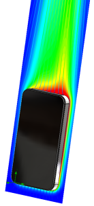
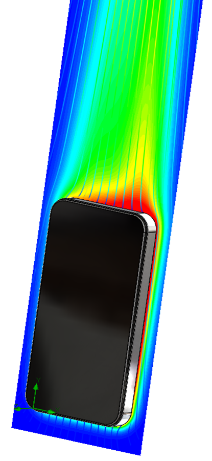
The case studied was video conferencing over LTE. This case was selected as it stresses the majority of the components in the unit: LTE modem, CPU (A4), eMMC, DDR, and imaging sensor (from the main camera). The total system power was 2.4 W (a rough estimate). All simulations were conducted at an ambient temperature of 25ºC.
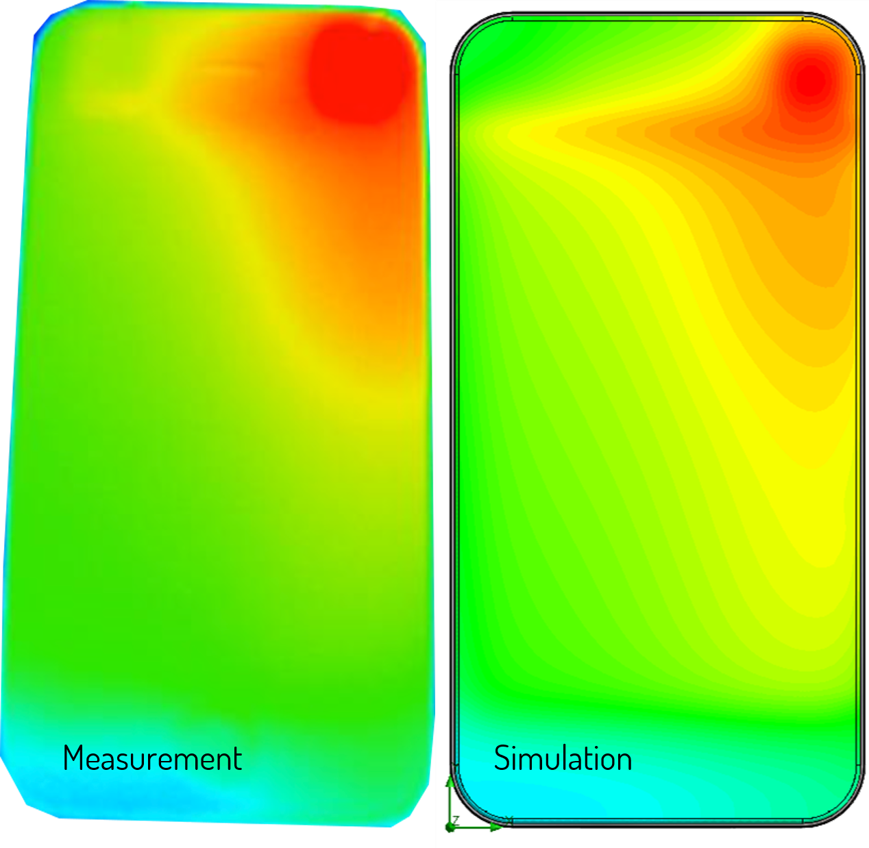
The pictures (bellow) shows a comparison between IR images taken from an iPhone 4 (left hand side) and the simulations (right hand side). The results are strikingly similar!
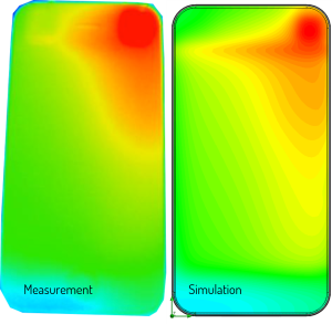
Figure 4. Comparisons between real measurements (left) and simulations (right) for the front cover glass.
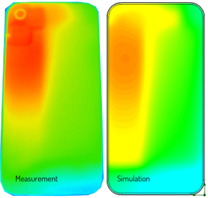
Figure 5. Comparisons between real measurements (left) and simulations (right) for the back cover glass.
These results were taken straight from the thermal model, using the assumed power of 2.4 W. The big red hot spot on the front cover glass (Figure 4) is caused by the imaging sensor of the main camera. In general, there is an excellent agreement between measurements and simulations.
The intention of this article was to get to this point. That is, corroborate that the thermal model for the iPhone is working, provides reasonable results and agrees with real measurements (checked).
We will use this thermal model to investigate different aspects of the thermal architecture in a future blog. We are also using this model to investigate on the effect of using protective cases (jackets, covers) and the benefits of the so-called cooling protective cases (my wife is thinking to buy one for her crazy-acting iPhone 5). I can say right now that they don’t work…wait, they might do better than a regular protective plastic case, maybe, but they cannot do better than the phone with no case. Heat is removed by convection and radiation, with case or no case, at the external housing of the phone, any layer of material that we add to it will simply add to the overall thermal resistance from chip to ambient (assuming the chip -whatever chip it is- is overheating). The only way to improve the dissipation outside the housing is adding a fan or two fans…wait, a protective case with two fans ? (what is Amited ?).
Stay tuned for the second part of this blog with a more detailed analysis of the iPhone thermal architecture.
 (1 votes, average: 5.00 out of 5)
 Loading...


i used to think that , apple’s phones are best and no issue of overheating. but this blog , i came to know good information. thanks for sharing it.
How did you estimate the power of each component ?
The contour profile seems to be similar but are the values close ?
Don’t you think assuming cans as stainless steel would have effected that ?
The power for components are just my own estimations. The actual temps might be different. I used SUS304 for all shielding cans.
Thanks!